Extending Ultrasonic Tank & Transducer Life: Preventing Cavitation Erosion
Executive Summary: Ultrasonic cleaners rely on intense cavitation bubbles to achieve powerful cleaning, but these same bubbles can erode tank walls and transducer surfaces over time. Understanding the physics of cavitation and system design helps prevent damage. Key factors include frequency (low-frequency 20–30 kHz yields large, forceful bubbles, high-frequency 40–120 kHz yields many small, gentle bubbles), power density, and bubble dynamics (imploding bubbles produce microjets and shock waves reaching thousands of atmospheres). Core system elements—piezo transducer design, mounting method, generator matching, and tank materials/coatings—must be optimized to handle these forces.
Cavitation erosion occurs when repeated bubble collapses fatigue material, causing microscopic pitting and cracks. Soft metals and weld seams are especially vulnerable. Prevention requires a combination of engineering controls (e.g. robust tank design, protective liners) and operating best practices (e.g. correct power and frequency settings, degassing, solution care). We present detailed strategies: from selecting stainless steel tanks and composite transducers, to using baskets and frequent filtration. We also recommend monitoring methods (visual inspection, impedance testing, acoustic sensing) and maintenance schedules. Actionable checklists and a mitigation techniques comparison table are included, plus a flowchart guiding responses to symptoms like pitting or noise. The goal is an ultrasonic cleaning system that delivers top performance while maximizing equipment lifespan.
Cavitation and Bubble Dynamics
Ultrasonic cleaning is powered by cavitation: alternating pressure waves in the liquid generate microscopic vapor bubbles during low-pressure cycles, which violently collapse in high-pressure cycles. Each collapsing bubble releases a tiny jet and shock wave. These impacts concentrate enormous energy into a small area – local temperatures near 10,000 °C and pressures up to 10,000 psi have been reported. The net effect is mechanical agitation that scrubs contaminant particles off surfaces.
- Frequency vs. Bubble Size: Lower ultrasonic frequencies (20–30 kHz) produce larger cavitation bubbles, which grow larger before collapse and release more energy upon implosion. These big bubbles create stronger microjets, making low-frequency cleaning highly effective against heavy soils (grease, carbon, paint). However, their force also heightens erosion risk. In contrast, higher frequencies (40–120 kHz) generate smaller, more numerous bubbles. The individual implosions are gentler, which is safer for delicate parts, but cleaning of very tenacious soils may take longer. Thus, frequency choice balances cleaning power versus surface safety.
- Power and Cavitation Intensity: Increasing ultrasonic power (wattage) boosts the number of bubbles without changing their size. More bubbles mean more simultaneous impacts across the surface, enhancing cleaning action. However, high power density can accelerate tank wear if not managed. Effective designs distribute power evenly (through multiple transducers and sweep frequencies) to avoid localized hotspots.
- Microjetting and Shock: When a cavitation bubble collapses near a solid boundary, it emits a high-speed liquid jet (up to ~300–500 m/s) and a shock wave into the material. These microscopic jets create fatigue micro-craters (pits) on the surface over time. The effect repeats millions of times per second over the tank surface. Over prolonged exposure, these tiny damages accumulate into visible pitting and cracks.
- Dead Zones and Standing Waves: Ultrasonic waves set up standing wave patterns in the tank. Certain zones (“antinodes”) receive intense cavitation, while “nodes” become quiet zones. If parts or coatings concentrate sound, or if tank walls resonate, some areas can suffer disproportionate erosion. Tank design must minimize dead zones (e.g. by placing transducers on multiple walls or moving baskets) to ensure uniform cavitation distribution.
In summary, cavitation delivers cleaning but is inherently erosive. Preventing damage begins with controlling how and where bubbles collapse: proper frequency, power control, and tank geometry are crucial foundations.
Ultrasonic System Technology
Achieving high cleaning performance while minimizing wear relies on sound system design:
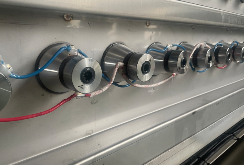
- Transducer Types: High-power machines may use composite transducers: stacks of several ceramic rings sandwiched by heavy metal end caps. Compared to monolithic types, composites have higher efficiency and better heat dissipation.
- Mounting and Coupling: Transducers are bonded to the tank wall (usually welded or epoxy-bonded). A flat, clean bond surface is essential. Mismatched bonding can cause partial decoupling and energy loss. The bond adhesive must withstand the cleaning chemicals and heat. Any air gap or weak glue invites mechanical fatigue. Operators should use dedicated ultrasonics epoxy or brass solder (for high-temp transducers) to secure each transducer.
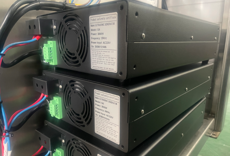
- Ultrasonic Generators and Matching: Generators supply high-frequency power (inverters at ~20–40 kHz typical). A good power supply has automatic frequency tracking and matching circuits to ensure each transducer runs at resonance. Mismatched frequency causes higher impedance, more heating, and less cavitation. Some systems allow sweep or multi-frequency modes to broaden the effective cleaning zone. Regularly check for “electrical faults” (e.g. failure codes for transducer connection). A sudden power drop or inability to reach output can signal a faulty transducer or connection.
- Tank Materials and Construction: Stainless steel is the standard for ultrasonic tanks. Tense’s TS series machines use SUS304 (stainless) for all wet parts, and their automated TSD model uses 2.5 mm SUS304 walls. Stainless resists both cavitation and chemicals. Thicker walls (2–3 mm) and fillet welds reduce stress. Note: some components (outer cladding, supports) may be painted mild steel, but only stainless contacts the bath. Never use soft metals (like aluminum) or unlined carbon steel; they erode rapidly under cavitation.
- Temperature Control: A built-in heater keeps the bath in an optimal range (often 40–60 °C). Warmer solution boosts cleaning speed, but too much heat (above ~65–70 °C) dampens cavitation and stresses components. Good systems have thermostats and timers to prevent overheating.
- Degassing and Filtration: Fresh water contains dissolved air, which cushions bubble collapse. Running the machine empty (or at low power) to degass for 10–15 minutes at startup (heating the bath) is recommended. Degassed fluid generates stronger, more consistent cavitation. For filtration, use external filters or skimmers: TENSE stresses that debris settles on the bottom and “dampens the ultrasonic waves”, so removing solids extends life. Many systems (like TS-UD) include multi-stage filtration to keep the liquid clean.
Cavitation Erosion Mechanisms
Over time, ultrasonic action causes cavitation erosion on any metal surface facing the cavitation field. The main mechanisms:
- Resonant Hotspots: If any area of the tank is overly excited (resonance from adjacent transducers), it experiences intensified cavitation. For example, corners, weld seams, or thin sections can resonate. These hotspots can erode faster, causing uneven wear patterns. Regularly inspect such areas.
- Mechanical Fatigue: Transducer elements themselves undergo alternating mechanical stress. A piezo disc expanding and contracting at ~40 kHz can fail by fatigue if heat isn’t managed. Lack of liquid coupling (dry run) or too high continuous power causes piezos to crack or delaminate. Tense warns of transducer overheating without cooling Also, frequent on/off cycling stresses solder joints.
In sum, erosion combines repeated mechanical impacts with any chemical attack. Hardening the surface (by thicker steel or coatings) can slow erosion, but the root cause is cavitation energy. Recognizing symptoms early is crucial: look for small pits, flaking metal, or a “sandblasting” noise from the tank.
Maintenance Schedule & Checklist
Daily/Before Use:
- Fill tank to proper level; ensure correct detergent concentration.
- Check for any foreign debris or residual tools inside tank; remove them.
- Inspect solution clarity; if heavily contaminated, prepare fresh batch.
- Confirm that baskets or fixtures are used for parts (never pile parts on tank bottom).
- Run a brief degas cycle (10 min heat, no parts) to stabilize cavitation
Weekly:
- Drain, filter, or replace cleaning solution. Skim oils and solids off the surface. Rinse and wipe the tank interior
- Inspect transducer mounts for signs of leakage or heat damage.
- Check generator lights/alarms for any error indications.
- Clean filters and pre-filters in circulation lines.
Monthly:
- Visually inspect entire tank interior and underside of lid for pitting or corrosion. Address minor pits immediately (sand/brush or weld patch).
- Verify that basket or part holders are secure and intact.
- Perform an impedance or megohm check on each transducer. Note any outliers.
- Verify temperature control accuracy (calibrate thermostat if needed).
Quarterly:
- Measure tank wall thickness at pre-marked locations. Compare to original specifications.
- Test cleaning performance with a check sample: if contamination removal slows, consider service.
- Lubricate hinges, check door seals (if applicable).
Annually (or after ~1000 hours):
- Replace worn transducers. As one guide suggests, plan replacement when cleaning efficiency falls below 80%
- Consider recoating or relining the tank if significant wear is evident.
- Perform a complete system calibration and preventive maintenance (follow manufacturer or third-party service guidelines).
- Review maintenance logs and update procedures as needed.
Replacement Thresholds:
- Transducers: Replace if output power drops by >20% or if resonance cannot be achieved. Also replace cracked or delaminated transducers immediately.
- Tank: Repair small pits. Replace tank (or liner) if any through-holes occur, or if cumulative metal loss compromises structural integrity (often ~30% thickness loss).
- Electronics: Generators are long-lived but can be recalibrated. Replace if out-of-range voltage/capacitance is observed or if one channel fails repeatedly.
Mitigation Techniques Comparison
| Mitigation Technique | Cost | Effectiveness | Downtime | Complexity |
| Proper Usage (baskets, filters) | Very Low | High (prevents many issues) | None | Low |
| Power/Duty Reduction | Low | Moderate | None | Low |
| Frequent Inspections/Repairs | Low | High (preventive) | Low | Low |
| Degassing & Clean Solutions | Low | High (improves cavitation control) | None | Low |
| Sacrificial Liners/Plates | Medium | Moderate-High | Medium (install) | Low-Moderate |
| Polymer Tank Liners (PTFE) | Medium | Moderate | Medium | Moderate |
| Hard Coatings (ceramic/metallic) | High | High (surface protection) | High | High |
| Anode/Corrosion Protection | Low | Low-Moderate | Low | Low |
| Transducer Upgrade | High | High (eliminates problem sources) | Medium | Moderate |
This table summarizes typical methods: emphasizing that basic maintenance and operating care (low cost, low downtime) offer high effectiveness in extending life. Engineering solutions like liners or coatings cost more and may require more downtime to apply, but they provide added protection in severe applications.